Rooftop solar panels are designed to capture as much sunlight as possible, but even a small amount of shade can reduce electricity production. Shadows from parapet walls, trees, water tanks, chimneys, neighboring buildings, antennas, HVAC equipment, and even adjacent solar panels can affect the performance of a photovoltaic (PV) system.
The challenge is that solar-panel shading does not always cause a proportional reduction in output. A shadow covering a relatively small portion of a module can create a much larger electrical loss because solar cells within a module are interconnected, and modules are commonly connected together in strings. The weakest current-producing section can therefore influence the output of the connected circuit.
For rooftop installations, the goal is not simply to install the maximum possible number of panels. We need to design the array so that sunlight reaches the modules for as much of the useful solar day as possible while minimizing electrical losses caused by unavoidable shade.
This guide explains how rooftop shading affects solar panels, how to identify shading sources, how panel placement and orientation can reduce losses, and how modern electrical technologies such as power optimizers and microinverters can help when some shading cannot be eliminated.
Rooftop Shading
Rooftop shading occurs when an object blocks direct sunlight from reaching one or more solar modules. Common rooftop shading sources include:
- Parapet walls
- Neighboring buildings
- Trees and branches
- Water tanks
- Chimneys
- HVAC units
- Satellite dishes
- Antennas
- Rooftop structures
- Solar-panel rows
- Poles and electrical equipment
- Temporary construction
- Nearby structures that become significant during winter
The location and movement of the shadow matter as much as its size. A shadow that falls on a panel for a few minutes early in the morning may have a relatively small annual impact, while a shadow that crosses the array during the middle of the day can be considerably more important. Near-shading analysis is therefore an essential part of rooftop PV design. Professional PV modeling can account for buildings, trees, rooftop equipment, row-to-row shading, and the changing position of the sun throughout the year.
Power Loss
Solar modules contain multiple photovoltaic cells connected electrically. In many conventional modules, cells are connected in series so that their voltages add together. When one section receives substantially less sunlight, its ability to produce current decreases. Because series-connected cells must carry essentially the same current, a shaded section can restrict the current available from the rest of the circuit.
Modern modules use bypass diodes to reduce the consequences of partial shading. These diodes provide an alternative current path around affected sections of the module. They help protect the module and prevent some of the shaded section from restricting the entire electrical path, but they do not make the shade disappear or recover all the energy that would have been produced under full sunlight. This is why we should never assume that a panel with 10% of its surface shaded will necessarily lose only 10% of its output.
A Simple Example
Suppose a rooftop array contains 12 modules connected into strings. If a tree shadow crosses one module, the affected module may produce substantially less current than the other modules. Depending on the module design, string configuration, inverter behavior, and exact shade pattern, the effect can extend beyond the visibly shaded portion.
The actual loss therefore depends on:
- How much of the module is shaded.
- Which cells are shaded.
- Where the shadow falls on the module.
- How long the module remains shaded.
- How the modules are wired.
- Whether bypass diodes are activated.
- Whether the system uses string inverters, optimizers, or microinverters.
- The position of the sun during the shading event.
Permanent Shading
Permanent shading comes from structures that are unlikely to move or disappear, such as neighboring buildings, tall parapet walls, chimneys, water tanks, elevator structures, and fixed HVAC equipment. These obstacles are the most predictable part of a shading analysis. Unlike seasonal vegetation, these structures cast consistent shadows based purely on the sun’s trajectory. Permanent obstacles should be identified and measured for height and width before the panel layout is finalized to ensure the most productive roof real estate is prioritized.
Vegetation Shading
Trees are particularly challenging because they grow and change shape. A tree that does not shade a rooftop today may become a major source of shade several years later. Branches can also produce irregular moving shadows that are difficult to predict using simple measurements. Furthermore, deciduous trees change their shading profile based on whether they have leaves or bare branches. We should evaluate the expected mature height and canopy of nearby trees rather than designing around their current size alone.
Inter-Row Shading
Solar panels can shade other solar panels. This commonly occurs when several rows of tilted modules are installed too close together. The front row casts a shadow toward the row behind it, particularly when the sun is low in the sky, such as during winter or in the early morning and late afternoon. Increasing row spacing reduces this effect, although it also increases the roof area required for a given number of panels. Reducing module tilt can also decrease the shadow cast by one row onto another, although the trade-off must be evaluated against the energy benefit of the selected tilt angle.
Moving Shading
Moving shadows are created by tree branches, clouds, nearby buildings, antennas, and utility structures. The same module may be shaded in the morning and completely exposed at midday. This makes time-based shading analysis more useful than simply looking at the roof at one particular moment. Professional installers use tools that calculate the "solar window," which is the period of the day when the sun is high enough to provide significant energy without being blocked by these moving obstructions.
Sun Position
The sun does not remain in the same position throughout the day or year. The direction and length of shadows change with the time of day, season, latitude, roof orientation, and height of surrounding objects. A relatively short rooftop obstacle can cast a long shadow when the sun is low in the sky. This is especially important during winter when the sun’s path is lower. For this reason, we should inspect shading during different times of day and different seasons rather than evaluating the roof under only one set of conditions.
Shading Assessment
Before installing solar panels, we should identify every object capable of blocking sunlight.
- Step 1: Inspect the Roof: Document roof dimensions, orientation, parapet height, and all rooftop equipment like water tanks and chimneys.
- Step 2: Identify Shadow-Producing Objects: Measure the approximate height and position of each obstacle.
- Step 3: Observe Shadows at Different Times: Observe the roof during morning, solar noon, and afternoon.
- Step 4: Use Solar Design Software: For larger systems, a 3D solar simulation is preferable. Modeling tools can estimate shading from buildings, trees, and terrain to provide a 3D representation of annual energy losses.
Panel Placement
The best layout depends on the roof and the source of the shade. We should prioritize areas with the longest duration of unobstructed sunlight rather than automatically filling every available roof section.
If a water tank consistently creates a large shadow, we can move panels farther away, change the array orientation, or reduce the number of panels in the affected area. Row spacing is equally critical. The correct design balances the energy gained from additional modules against the energy lost through inter-row shading. Sometimes, removing one or two panels from a "dead zone" increases the overall efficiency of the entire string.
Orientation
Module orientation (landscape vs. portrait) can influence how a partial shadow affects the electrical output. Depending on the location and direction of the shadow, landscape installation can sometimes reduce electrical shading losses compared with portrait installation. This is because most modules have bypass diodes that divide the panel into vertical or horizontal sub-sections. If a shadow only covers one sub-section, the others can still function. Therefore, we should not choose portrait or landscape orientation solely for aesthetic reasons when shading is present.
Power Optimizers
Power optimizers are module-level DC electronics (MLPE) designed to optimize the operating point of individual modules. They are useful when different panels experience different conditions. In a traditional system, one shaded panel can drag down the performance of the entire string. Optimizers allow each module to work at its maximum power point independently. Research confirms that individual maximum-power-point tracking (MPPT) can help address mismatch caused by shading, but they are not a replacement for good design—removing the shade is always the first choice.
Microinverters
Microinverters convert DC electricity to AC at the module level. This differs from a string-inverter architecture where multiple modules feed a common DC string. Microinverters are attractive for complex roofs with multiple orientations or localized shading because the performance of one module is managed individually rather than sharing a series-string current limit. Shading losses and shared AC limits still depend on the system design. They also provide module-level monitoring, allowing homeowners to see exactly how much energy each panel is producing in real-time.
Bypass Diodes
Bypass diodes are a critical protection mechanism. Without them, a shaded cell in a series circuit can experience reverse-bias conditions and become a "hot spot." A bypass diode provides an alternative path around a shaded part of the module. This helps reduce electrical stress, limit shading-related losses, and protect cells from localized overheating. While they are an essential safety and performance feature, they do not recover the energy lost to shade; they simply prevent the shaded section from stopping the entire panel or string.
Hot Spots
A hot spot occurs when a shaded cell is forced to conduct current generated by unshaded cells. Instead of producing electricity, the shaded area dissipates energy as heat. This localized heating can cause cell damage, encapsulant browning, and even glass cracking. Shading should therefore be treated as an equipment-protection issue as well as an energy-yield issue. Persistent, sharp shadows (like those from a leaf or a bird dropping) are often more dangerous for hot spots than large, soft shadows because they create higher current differentials.
Parapet Walls
Parapet walls are common shading obstacles, especially on commercial flat roofs. Their impact depends on wall height, panel tilt, and the distance from the wall. A high parapet positioned in front of the first panel row can cast a significant shadow during the morning and afternoon. We can reduce this problem by increasing the setback (distance from the wall), adjusting the panel tilt to be lower, or modeling the shadow movement throughout the year to find the "no-go" zone for panel placement.
Water Tanks
Water tanks are often the tallest objects on a residential roof and can create concentrated shadows. The tank’s height and distance from the array are more important than its footprint alone. If a tank location is fixed, the array should be positioned so the tank’s shadow crosses as few modules as possible during the site’s most productive hours, as assessed across seasons. Designers should also ensure there is enough space for maintenance workers to access the tank without walking on or shading the panels.
Trees
Trees grow, and their shading impact increases over time. Before installation, evaluate the current height, expected mature height, and canopy width. Pruning can help, but it is a recurring maintenance task. Where trees cannot be altered due to local regulations or environmental value, the solar design must adapt. This may mean using microinverters or simply leaving the most shaded sections of the roof empty to avoid wasting money on panels that won’t produce.
Reducing Loss
The most effective strategy is a combination of physical and electrical design choices:
- Remove Avoidable Obstacles: Relocate antennas or satellite dishes.
- Optimize Spacing: Ensure rows don’t shade each other.
- Change Orientation: Use landscape or portrait based on shadow direction.
- Use Separate Strings: Group shaded modules on one string and unshaded on another.
- Use MLPE: Deploy optimizers or microinverters for unavoidable shade.
- Simulation: Use software to predict and avoid the worst shading zones.
Soiling
Shading and soiling can look similar on a production graph, but they are different. Shading is an external object blocking light, while soiling is the accumulation of dust, dirt, or bird droppings on the module surface. In dusty environments, soiling can worsen shading effects. A shaded module that is also dirty will experience extreme performance drops. Regular cleaning and maintenance are essential, especially for low-tilt panels that don’t benefit as much from "self-cleaning" during rain.
Yield Calculation
To isolate shading loss, compare modeled energy with and without shade under otherwise identical conditions. Actual production also reflects weather, dirt, faults and other losses. A simple formula is: Shading Loss (%) = (Unshaded Energy − Shaded Energy) ÷ Unshaded Energy × 100. For accurate design, professional software uses irradiance data and 3D modeling. Visible shaded area does not directly establish the electrical energy loss. Modeling accounts for these non-linear electrical behaviors.
Panel Tilt
Panel tilt affects both energy capture and the shadow the panel casts. Higher tilt increases the shadow length behind the panel, requiring wider row spacing. Lower tilt reduces inter-row shading but might capture less energy depending on the latitude and season. Designers must find the "sweet spot" where the tilt maximizes energy without causing excessive shading on the row behind it or making the panels more susceptible to dust accumulation.
Design Workflow
A professional design workflow follows these stages:
- Roof Survey: Measure everything.
- Obstacle Identification: Map chimneys, tanks, and trees.
- Path Analysis: Use a SunEye or software to track the sun’s path.
- 3D Modeling: Create a digital twin of the roof and obstacles.
- Layout Optimization: Place panels in the "brightest" spots.
- Architecture Selection: Decide on string inverters, optimizers, or microinverters.
Shaded Roofs
Can solar panels work on a shaded roof? Yes. The key is distinguishing between manageable partial shade and persistent heavy shade. A roof with morning or afternoon shade may still be viable, but an annual energy estimate is needed to judge the impact. Modern electronics like microinverters make these "sub-optimal" roofs much more viable than they were ten years ago. It’s all about the annual return on investment rather than 100% perfection.
Capacity Compensation
Should you add more panels to compensate for shade? Sometimes. If an area is only slightly shaded, adding an extra module can make up for the lost kilowatt-hours. However, adding panels in a heavily shaded area is often a waste of money. It is better to use higher-efficiency panels in the unshaded areas or optimize the layout before simply "throwing more hardware" at the problem. Compensation should be an economic decision based on the cost per kWh.
Performance Monitoring
Monitoring is vital for shaded systems. It allows you to see recurring dips in production that suggest a predictable shadow. If a specific string or module drops every day at 2 PM, you can look for the cause—perhaps a new branch has grown or a neighbor has installed a satellite dish. Comparison between modules is the easiest way to diagnose shading versus a technical fault like a loose wire or a failing inverter.
Common Mistakes
Common pitfalls include installing panels too close to parapets, ignoring future tree growth, and using a single string for modules with vastly different shading profiles. Relying on a single site visit at noon can also be misleading, as it doesn’t show the long shadows of morning or evening. Finally, many people treat optimizers as a "magic bullet"—while they help, they cannot create power out of darkness. Good physical placement remains the foundation of a high-performing system.
Final Takeaway
Rooftop shading is a critical factor in solar performance. Because PV cells are interconnected, shading behavior is non-linear and complex. The most effective approach is prevention through a thorough survey, 3D modeling, and strategic layout. By combining physical setbacks with modern electronics like microinverters or optimizers, you can maximize energy production even on challenging rooftops. A successful solar system isn’t the one with the most panels—it’s the one that captures the most sunlight over its service life.
Related solar guides and reference documents
Continue with our solar inverter buying guide, solar system sizing guide, safe panel cleaning guide and battery backup calculation guide.
Reference: PVsyst shading documentation. Use the exact model and regional documents for your equipment. Grid-connected designs must meet the current requirements of the relevant electricity distribution company.
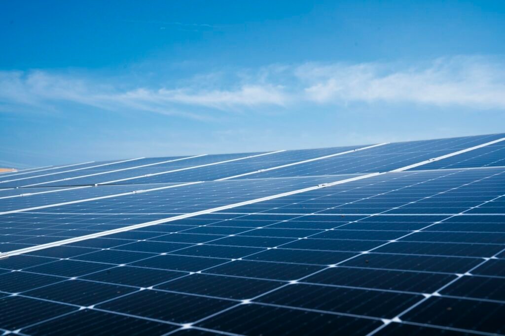
Featured stock photo: Soren H / Unsplash. The image is illustrative and does not identify a Pakistani installation or a recommended equipment model.